A.K. Dokoupil(1), M.G. Beker (1), T. Peters (1), H.L.M. Heeres(1), A. Bertolini (2)
For autonomous positioning and navigation, high-accuracy inertial sensor data is needed. Low-cost micro-electrical mechanical systems (MEMS)-based inertial measurement units (IMUs) available today do not provide the required level of accuracy. We present a novel MEMS accelerometer that provides acceleration data with ultra-low noise levels. The advantage of such a sensor for satellite positioning is demonstrated by simulations on low-thrust orbital manoeuvres.
MEMS accelerometer
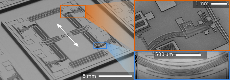
Our MEMS accelerometer uses a mass-spring system to measure acceleration. A prototype MEMS accelerometer is presented below.
Read-out Electronics
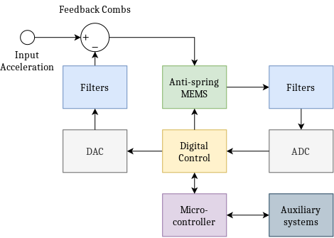
To increase dynamic range, the sensor is operated in closed loop where input acceleration is counteracted by applying an electrostatic force to the proof mass. A block diagram of this control system is shown on the right. Here the position is obtained using a digital control block, and feedback is applied to keep the proof mass centred. This feedback signal is exactly equal to the input acceleration and is transmitted to the auxiliary systems.
Anti-spring technology
The concept of geometric anti-spring suspension technology, originating from the ‘macro’ gravitational wave detector community, is applied at the micro-scale for the MEMS accelerometer.
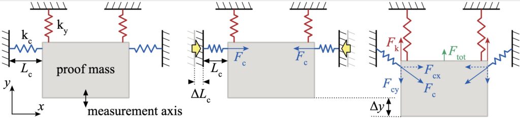
- (A) A proof mass is suspended by four springs: two springs parallel and two springs perpendicular to the measurement axis.
- (B) The anti-spring effect is achieved by pre-loading the springs perpendicular to the measurement axis. The pre-loaded springs exert a static compression force, Fc, on the proof mass.
- C) Displacing the proof mass along the measurement axis will result in a force Fcy=-2Fc∙∆y/Lc. This force cancels part of the restoring force exerted by the suspension springs, Fk=ky∙∆y, and effectively lowers the total stiffness over the measurement axis. The stiffness in the sensing direction can be controlled by adjusting Fc.
Performance
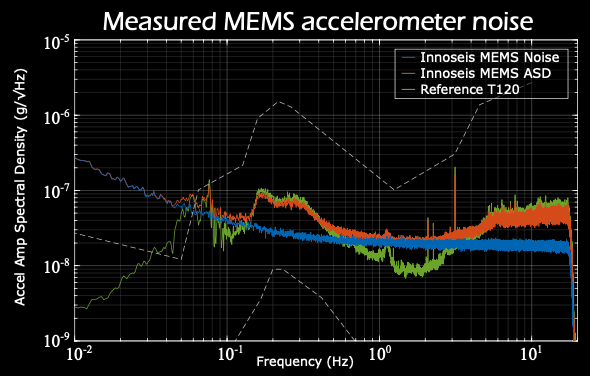
The power spectral density of MEMS data recorded over 24 hours in an environment with limited background vibration is shown below. The synced signal for a ‘Trillium 120-s’ seismometer is included for reference. The MEMS noise floor was derived from these signals using three-channel correlation analysis. From this data, it is estimated that the velocity random walk, or white noise, is roughly 20 ng√Hz and flicker noise is 28 ng.
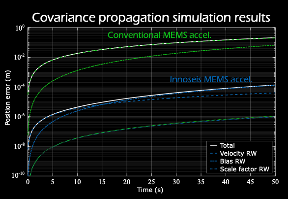
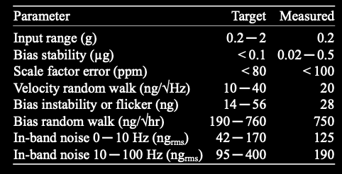
Covariance propagation simulation results for a conventional and an anti-spring MEMS accelerometer are plotted above. The accumulated position error is calculated during a constant-thrust (7 μg) manoeuvre of 50 seconds. It is shown that from the modelled disturbances, the largest contribution to the error budget is from the bias random walk. The position error for the conventional accelerometer accumulates rapidly while the anti- spring accelerometer shows improved positioning accuracy by over three orders of magnitude. All target and measured specifications are summarised in the table below.
Summary and outlook
A novel sensor was developed with the application in next-generation inertial navigation for satellites and other spacecraft. Measurements conducted at a low-vibration environment have shown improved performance and simulation results have demonstrated the added value. In the case of orbit maintenance of a geostationary spacecraft, the new sensors monitor thrust manoeuvres more precisely, allowing autonomous station keeping and reducing the need for ground-based orbit determination. Future activities will extend the performance analysis of the accelerometer and will include elements such as thermal, shock, and radiation tolerance.
[This work was carried out under a programme of, and funded by, the European Space Agency. Any views expressed can in no way be taken to reflect the official opinion of the European Space Agency]